Optical waveguide metrology and index of refraction mapping

Single-shot mapping of refractive index in waveguides and photonic devices

Optical waveguides are largely used in photonic devices and systems, due to their low optical loss. The refractive index profile distribution of optical waveguides is the key parameter as it determines the insertion losses and propagating modes. Based on its quantitative phase imaging (QPI) technique, Phasics offers high-accuracy metrology instruments for measurement of refractive index variations. Accurate refractive index measurement is necessary for the development, the optimization, and the quality monitoring of produced photonic devices. As a non-destructive method, QPI gives a precise refractive index profile of waveguides. The SID4-Imaging system is adapted for measurements on either optical fiber or laser-written waveguides.

  • ▽ Implementation on any optical microscope

    index of refraction mapping setup - SID4 is integrated on an optical microscope

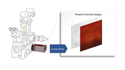
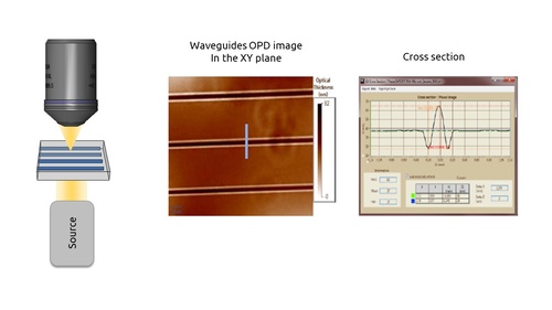
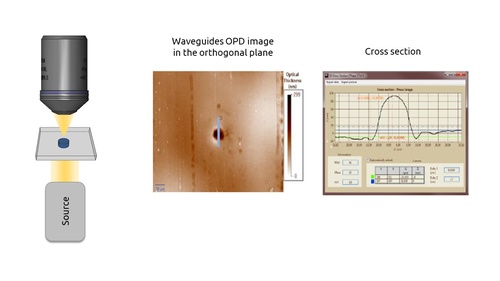
    A Phasics quantitative phase imaging (QPI) camera is installed on a classical bright-field microscope. No modification of the microscope is required.  Phasics expert software outputs optical path difference (OPD) maps that can be easily converted to a change of refractive index map as follows: OPD = (n2 – n1) x d, with n2 and n1 being the respectives indices of refraction of the surrounding material and the waveguide and d being he thickness of the index change area.                                   

  • ▽ Waveguide measurement setup

    Waveguide measurement configuration (XY)

    Waveguide imaging can be done in two different configurations: in XY or in the orthogonal plane. Phasics quantitative phase camera measures the optical path difference (OPD)  generated by the waveguide. Knowing the mechanical size of the waveguide, it is straighforward to retrieve refractive index values.

    OPD (nm) = (n waveguide – n susbtrate) x mechanical thickness (nm)                                  

  • ▽ Waveguide measurement setup (orthogonal)

    Waveguide measurement setup (orthogonal)

    In this representation, the waveguide is sliced and measured in the orthogonal configuration.                       


Measurement Examples

Optical Path Difference OPD map of a laser inscribed optical waveguide measured with QWSLI (SID4-HR wavefront sensor)

Optical Path Difference (OPD) map

Index of refraction change map of a laser inscribed optical waveguide measured with QWSLI (SID4-HR wavefront sensor)

Changes of refractive index map

Change of refractive index measurements created using different fluencies measured with QWSLI (SID4-HR wavefront sensor)

Waveguide design validation

Advantages

High capabilities

  • Diffraction limit spatial resolution
  • Highly reproducible
  • Extremely sensitive

Powerful approach

  • Non destructive
  • 2D mapping
  • Real time calculation

Easy to use

  • Compatible with any microscope
  • Compact
  • Plug and play

Download


Related Products

Related Markets

Material science AR/VR

   iconepublications   Visit our publication page

Sign up to receive the latest updates and news